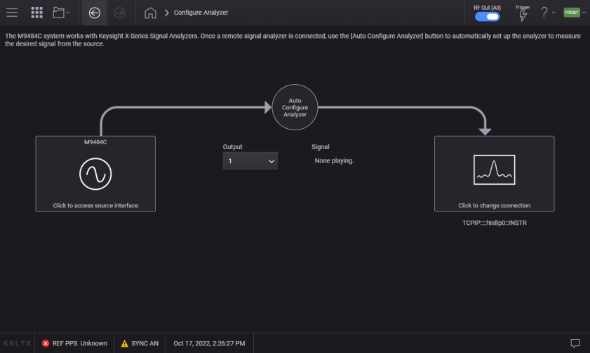
Use the triple bar icon on the top left of the display to access the Configure Analyzer selection. The Configure Analyzer screen is used for performing generation-to-analysis workflow. The "Auto Configure Analyzer" button will automatically transfer the setup from the Source to a Keysight X-Series Signal Analyzer, in order to measure the desired signal from the Source. If you are generating a 3GPP 5G New Radio, NR-V2X, or Custom IQ signal via the Applications menu of the signal generator, and the corresponding application is licensed on the analyzer, the analyzer will perform demodulation of the signal. Otherwise, the analyzer will auto-tune on the signal being generated. The Keysight X-Series Signal Analyzer requires firmware version x.35.00 or greater for the demodulation to be performed.
|
GUI Location |
System Menu (triple bar icon) > Configure Analyzer |
|
Initial S/W Revision |
A.01.00 |
|
Modified S/W Revision |
A.08.00 |
Specify Device for Auto Configure Analyzer
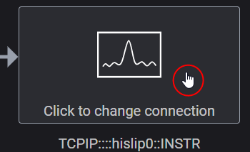
The "Click to change connection" box opens the Remote Instrument screen, which provides settings for remotely connecting to the Keysight X-Series signal analyzer. The default values for the signal analyzer are pre-populated. Refer to your signal analyzer if the values are different from the default.
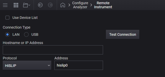
This checkbox enables the Device List to be the sole method of specifying a Spectrum Analyzer to be used for a channel’s Auto Configuration.
A ![]() screen appears, showing the name and type of the current device, if any, and a Configure Device button.
screen appears, showing the name and type of the current device, if any, and a Configure Device button.
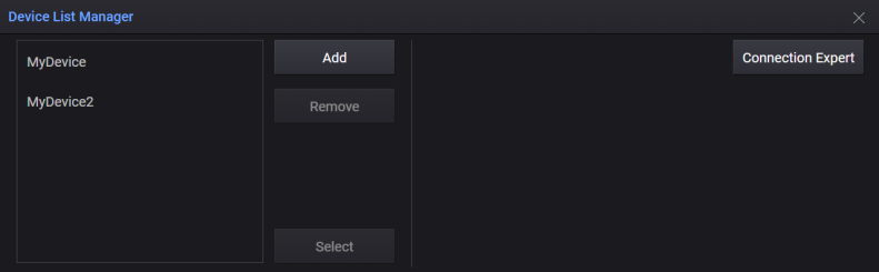
The Configure Device button takes you to the ![]() Device List Manager screen where you can select and configure other devices.
Device List Manager screen where you can select and configure other devices.
To configure external devices in the Device List, see Device List.
|
GUI Location |
System Menu (triple bar icon) > Configure Analyzer > Click to change connection > select Use Device List |
|
SCPI Command |
[:SOURce][:RF<channel>]:ASANalyzer:DLISt ON|OFF|1|0 [:SOURce][:RF<channel>]:ASANalyzer:DLISt? |
|
SCPI Example |
RF3:ASAN:DLIS ON |
|
Preset |
OFF |
|
State Saved |
Yes |
|
Range |
ON | OFF | 1 | 0 |
|
Initial S/W Revision |
A.12.00 |
Specifies a Spectrum Analyzer from the Device List to be used for the specified channel’s Auto Configuration.
To configure external devices in the Device List, see Device List.
|
GUI Location |
System Menu (triple bar icon) > Configure Analyzer > Click to change connection > select Use Device List checkbox > Configure Device > Device List Manager |
|
SCPI Command |
[:SOURce][:RF<channel>]:ASANalyzer:DEVice <name string> [:SOURce][:RF<channel>]:ASANalyzer:DEVice? |
|
SCPI Example |
RF3:ASAN:DEV "mySpectumAnalyzer" |
|
Notes |
If the specified device does not exist in the Device List, the following error will be raised: -220,"Parameter error; Specified device does not exist" If the specified device is not a Spectrum Analyzer the following error will be raised: -220,"Parameter error; Auto Configure Analyzer requires a Spectrum Analyzer device type" |
|
Couplings |
If the device currently selected from the Device List is removed, this setting will default to NONE Value will only be utilized by hardware when Use Device List for Auto Configure Analyzer is set to ON. |
|
Preset |
NONE |
|
State Saved |
Yes |
|
Initial S/W Revision |
A.12.00 |
Select a LAN or USB physical communication connection to the analyzer.
|
GUI Location |
System Menu (triple bar icon) > Configure Analyzer > Click to change connection > Connection Type |
Set LAN Address
Enter the Hostname or IP Address of the analyzer. the LAN address is saved during Save User Preset, allowing you to use User Preset to easily restore the address after startup.
Set Protocol
The values of the protocol settings are standard values for the Keysight X-Series signal analyzers. Changes to the values persist across power-cycling and are not changed by Preset. Use Restore System Settings to Default to return the values to their defaults. The protocol in use much match the setting in the analyzer’s configuration.
The default protocol is HiSLIP which has the highest throughput of the LAN choices.
After connecting your device to a USB port, select it from the drop-down menu. You can also refresh the list of USB connected devices, if necessary.
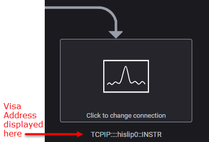
Use this immediate action to check the communication connection to the analyzer. If successful, a message briefly appears and the VISA address is displayed below the ![]() analyzer block in the Configure Analyzer screen. If unsuccessful, a message briefly appears and is logged in the message queue.
analyzer block in the Configure Analyzer screen. If unsuccessful, a message briefly appears and is logged in the message queue.
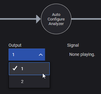
On instruments with more than one channel, you indicate which channel is directed to the signal analyzer.
|
GUI Location |
System Menu (triple bar icon) > Configure Analyzer > Output |
|
SCPI Command |
[:SOURce]:SCONfigure:OUTPut <channel> [:SOURce]:SCONfigure:OUTPut? |
|
SCPI Example |
SCON:OUTP 1 |
|
Notes |
The maximum selection is based on the configuration of the instrument. Use the query SOUR:RF:COUN? to determine the maximum value for the instrument being controlled. When Use Device List for Auto Configure Analyzer is set to OFF, Visa Address of Receiver is used to specify a Spectrum Analyzer, see VISA Address of Receiver. When Use Device List for Auto Configure Analyzer is set to ON, Device for Auto Configure Analyzer is used to specify a Spectrum Analyzer, see Specify Device for Auto Configure Analyzer. |
|
Preset |
1 |
|
Min |
1 |
|
State Saved |
Yes |
|
Initial S/W Revision |
A.01.00 |
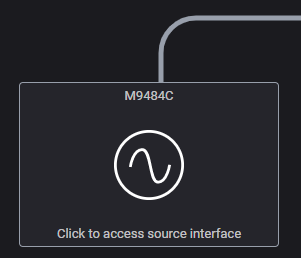
The diagram for the signal generator lists the configuration of the Signal and Frequency for each channel. Selecting the source diagram returns to the generator’s main screen.
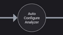
Select the Auto Configure Analyzer control to send the signal generator’s settings to the signal analyzer.